Effects of Electromagnetic Shielding in Electron Microscopy Lab Environment (Part 3): Comparison of Several Methods for Improving the Electromagnetic Environment
The environment of an electron microscopy lab does not directly impact the electron microscope itself but rather affects the imaging quality and overall performance of the microscope. During the operation of an electron microscope, the fine electron beam needs to travel in a high vacuum environment, covering a distance of 0.7 meters (for Scanning Electron Microscope) to over 2 meters (for Transmission Electron Microscope). Along the path, external factors such as magnetic fields, ground vibrations, noise in the air, and airflows can cause the electron beam to deviate from its intended path, leading to a degradation in imaging quality. Therefore, specific requirements need to be met for the surrounding environment.
Passive low-frequency electromagnetic shielding primarily involves two methods, which differ in the shielding material used: one method uses high-permeability materials (such as steel, silicon steel, and mu-metal alloys), and the other method uses high-conductivity materials (such as copper and aluminum). Although the working principles of these two methods are different, they both achieve effective reduction of environmental magnetic fields.
A. The high-permeability material method, also known as the magnetic circuit diversion method, works by enclosing a finite space (Region A) with high-permeability materials. When the environmental magnetic field strength is Ho, the magnetic reluctance of the high-permeability material is much smaller than that of air (common Q195 steel has a permeability of 4000, silicon steel ranges from 8000 to 12000, mu-metal alloys have a permeability of 24000, while air has an approximate value of 1). Applying Ohm's law, when Rs is much smaller than Ro, the magnetic field strength within the enclosed space (Region A) decreases to Hi, achieving demagnetization (see Figure 1 and Figure 2, where Ri represents the air reluctance within space A, and Rs represents the shielding material reluctance). Inside the shielding material, the magnetic domains undergo vibration and dissipate magnetic energy as heat under the action of the magnetic field.
Since silicon steel and mu-metal alloys exhibit anisotropy in permeability and cannot be hammered, bent, or welded during construction (although theoretically, heat treatment can improve these properties, it is impractical for large fixed products), their effective performance is significantly reduced. However, they can still be used for supplementary or reinforcement purposes in certain special areas without hammering, bending, or welding.
High-permeability materials are expensive, so they are generally not extensively used in electron microscope shielding and are only seen in a few specific areas (such as door gaps, waveguide openings, etc.).
The effectiveness of the magnetic circuit diversion method is roughly linearly related to the thickness of the shielding material, which can theoretically be infinitely thin.
B. The high-conductivity material method, also known as the induced magnetic field method, works by enclosing a finite space with high-conductivity materials. The environmental magnetic field acts on the shielding material through its electric field component, inducing an electromotive force, which in turn generates an induced current and an induced magnetic field. Based on the fundamental principles of electromagnetics, this induced magnetic field is equal in magnitude (slightly smaller due to resistance) and opposite in direction to the original magnetic field (with a slight phase lag). Thus, the magnetic field within the finite space is counteracted and weakened, achieving demagnetization.
Further understanding of the induced magnetic field method can be gained by considering the operation of a three-phase induction motor, which provides insights into the working principles of induced magnetic fields. It is important to note that an asynchronous squirrel cage motor cannot achieve the rotating magnetic field (50Hz × 60s = 3000 RPM) because the squirrel cage bars cannot cut magnetic lines, thus preventing the generation of induced currents, induced magnetic fields, and driving force.
The effectiveness of the induced magnetic field method is independent of the thickness of the shielding material within a certain range.
C. Common characteristics of both methods: Full penetration welding is required, and the height of the weld seam should not be less than the thickness of the shielding material. Attention must be paid to the design of openings at various scales and waveguide ports. Whether the design/production is successful will greatly affect the shielding effectiveness (applying the "Weakest Link" theory to shielding). It is also important to note that the vibration of the electron microscope in the shielding room should not exceed that of the surrounding environment (there have been cases where the magnetic field passed the inspection but the vibration increased compared to the original, causing non-compliance).
From their basic working principles, it is evident that both the magnetic circuit diversion method and the induced magnetic field method are ineffective for DC fields. They are also generally ineffective for near-DC fields (in such cases, an active demagnetizer is necessary to improve near-DC electromagnetic interference).
A.Compare the two methods in a table:
|
Advantages |
Disadvantages |
Magnetic Circuit Diversion |
Lower cost, adjustable shielding effectiveness (theoretically infinite)
|
Heavier weight |
Easy to construct and produce.
|
Slightly more difficult to construct and produce.
|
|
Induced Magnetic Field |
Lighter weight (aluminum) |
Use non-ferromagnetic materials |
|
Limited shielding effectiveness due to its fundamental mechanism.
|
Upon careful analysis, the magnetic circuit diversion method is more advantageous. The passive low-frequency demagnetizer has advantages such as small size, lightweight, low cost, no impact on the environment, and the possibility of post-purchase installation.
However, one important point to note is that magnetic shielding is often an "entrusted" project, meaning that it often includes electrical, water, air conditioning, lighting, and network systems, as well as monitoring, during the construction process. Therefore, if there is a need for remodeling, it offers a higher cost-performance ratio.
Overall, passive magnetic shielding has better effectiveness than demagnetizers, but due to the aforementioned reasons, demagnetizers may still be the only option in some environments.
For Scanning Electron Microscope, the difference between these methods is not significant. However, for Transmission Electron Microscope, it is recommended to use magnetic shielding as much as possible, as the requirements for magnetic fields are generally higher compared to Scanning Electron Microscope.
Stable, Versatile, Flexible, and Efficient The CIQTEK SEM4000X is a stable, versatile, flexible, and efficient field emission scanning electron microscope (FE-SEM). It achieves a resolution of 1.9nm@1.0kV, and easily tackles high-resolution imaging challenges for various types of samples. It can be upgraded with an ultra-beam deceleration mode to enhance low-voltage resolution even further. The microscope utilizes multi-detector technology, with an in-column electron detector (UD) capable of detecting SE and BSE signals while providing high-resolution performance. The chamber-mounted electron detector (LD) incorporates crystal scintillator and photomultiplier tubes, offering higher sensitivity and efficiency, resulting in stereoscopic images with excellent quality. The graphic user interface is user-friendly, featuring automation functions such as automatic brightness & contrast, auto-focus, auto stigmator, and automatic alignment, allowing for rapid capture of ultra-high resolution images.
Learn MoreHigh Resolution under Low Excitation The CIQTEK SEM5000Pro is a Schottky field emission scanning electron microscope (FE-SEM) specialized at high resolution even under low excitation voltage. Employing an advanced "Super-Tunnel" electron optics technology facilitates a crossover-free beam path together with an electrostatic-electromagnetic compound lens design. These advancements reduce spatial charging effect, minimize lens aberrations, enhance imaging resolution at low voltage, and achieve a resolution of 1.2 nm at 1 kV, which allows for direct observation of non-conductive or semi-conductive samples, effectively reducing sample irradiation damage.
Learn MoreHigh-speed Scanning Electron Microscope for Cross-scale Imaging of Large-volume Specimens CIQTEK HEM6000 facilities technologies such as the high-brightness large-beam current electron gun, high-speed electron beam deflection system, high-voltage sample stage deceleration, dynamic optical axis, and immersion electromagnetic & electrostatic combo objective lens to achieve high-speed image acquisition whilst ensuring nano-scale resolution. The automated operation process is designed for applications such as a more efficient and smarter large-area high-resolution imaging workflow. The imaging speed can reach over 5 times faster than a conventional field emission scanning electron microscope (FESEM).
Learn MoreEasy-to-use Scanning Electron Microscope Even for Novices The CIQTEK SEM2100 SEM Microscope features a simplified operating process, adheres to industry standards and user habits in its "User Interface" design. Despite the minimalist software interface, it provides comprehensive automated functions, measurement and annotation tools, image post-processing management capabilities, optical image navigation, and more. The design of SEM2100 perfectly realizes the idea of "Simplicity without sacrificing functionality".
Learn More120kV Field Emission Transmission Electron Microscope (TEM) 1. Divided Workspaces: Users operate TEM in a divided room with comfort reducing environmental interference to TEM. 2. High Operational Efficiency: Designated software integrates highly automated processes, allowing efficient TEM interaction with real-time monitoring. 3. Upgraded Operational Experience: Equipped with a field emission electron gun with a highly automated system. 4. High Expandability: There are sufficient interfaces reserved for users to upgrade to a higher configuration, which meets diverse application requirements.
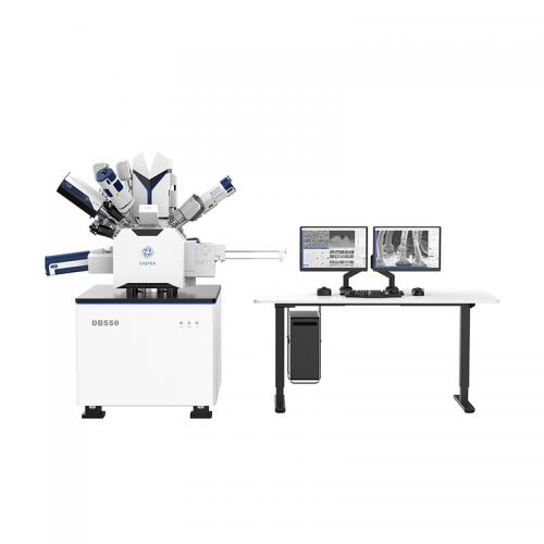
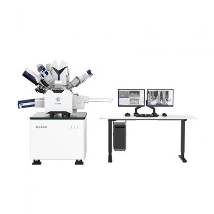
Learn MoreField Emission Scanning Electron Microscope (FE-SEM) with Focused Ion Beam (FIB) Columns The CIQTEK DB550 Focused Ion Beam Scanning Electron Microscope (FIB-SEM) has a focused ion beam column for nano-analysis and specimen preparation. It utilizes “super tunnel” electron optics technology, low aberration and non-magnetic objective design, and has the “low voltage, high resolution” feature to ensure its nanoscale analytical capabilities. The ion columns facilitate a Ga+ liquid metal ion source with highly stable and high quality ion beams to ensure nanofabrication capabilities. The DB550 is an all-in-one nano-analysis and fabrication workstation with an integrated nano-manipulator, gas injection system, and user-friendly GUI software.
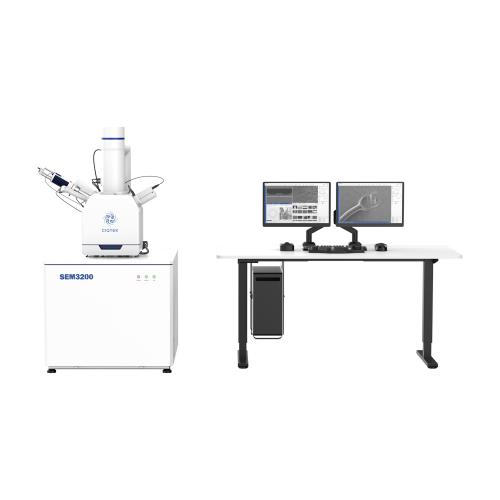
Learn MoreHigh-performance and Universal Tungsten Filament SEM Microscope The CIQTEK SEM3200 SEM Microscope is an excellent general-purpose Tungsten Filament Scanning Electron Microscope (SEM) with outstanding overall capabilities. Its unique Dual-anode electron gun structure ensures high resolution and improves image signal-to-noise ratio at low excitation voltages. Furthermore, it offers a wide range of optional accessories, making the SEM3200 a versatile analytical instrument with excellent expendabilities.
Learn More